
Description
Specification
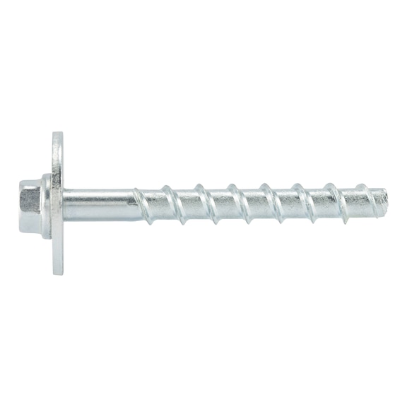
Highest load capacities and efficient mounting. Ideal for mounting wood structures (large washer as per DIN 440) in concrete, zinc-plated steel | Extremely flexible to use due to three anchoring depths
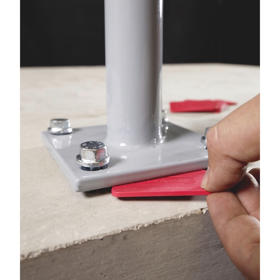
Fastening can be adjusted up to twice after installation, for example in order to align railings or anchor plates (please refer to the assembly guide)
Very high loads
Smallest spacing and edge distance thanks to very low expansion effect
Very fast and easy assembly and immediately load-bearing | Extremely flexible to use due to three anchoring depths | Fastening can be adjusted up to twice after installation, for example in order to align railings or anchor plates (please refer to the assembly guide) | Very high loads | Smallest spacing and edge distance thanks to very low expansion effect | Very fast and easy assembly and immediately load-bearing | Proof of Performance | European Technical Assessment ETA-16/0043 for individual fixing point, option 1, cracked and uncracked concrete: | Static and quasi-static effects
Seismic exposure, performance categories C1 and C2
Fire resistance R30, R60, R90, R120 | Static and quasi-static effects | Seismic exposure, performance categories C1 and C2 | Fire resistance R30, R60, R90, R120 | DIBt National technical approval/general type approval Z-21.1-2075 as bonded screw anchor for anchoring in concrete | Use in combination with injection mortar WIT-BS as bonded screw anchor WIT-BS
In reinforced and non-reinforced and cracked and uncracked concrete C20/25 to C50/60 | Use in combination with injection mortar WIT-BS as bonded screw anchor WIT-BS | In reinforced and non-reinforced and cracked and uncracked concrete C20/25 to C50/60 | Notice | From size 8, we recommend the use of a suitable tangential impact screwdriver for installation. The recommended maximum nominal torque must be observed. | Application area | Wooden structures
Adjustment – subsequent aligning possible. | Wooden structures | Wooden structures | Adjustment – subsequent aligning possible. | Adjustment – subsequent aligning possible. | Adjustment – subsequent aligning possible. | Create the drill hole
Clean the drill hole
Place screw
Screw in the screw
Considered installed when the head is close fitting | Create the drill hole | Create the drill hole | Create the drill hole | Clean the drill hole | Clean the drill hole | Clean the drill hole | Place screw | Place screw | Place screw | Screw in the screw | Screw in the screw | Screw in the screw | Considered installed when the head is close fitting | Considered installed when the head is close fitting | Considered installed when the head is close fitting | Screw out the screw max. 2x each by max. 10 mm. Underlay. Screw in
Considered installed when the head is close fitting. Lining max. 10 mm. The required embedment depth must be maintained as a minimum | Screw out the screw max. 2x each by max. 10 mm. Underlay. Screw in | Screw out the screw max. 2x each by max. 10 mm. Underlay. Screw in | Screw out the screw max. 2x each by max. 10 mm. Underlay. Screw in | Considered installed when the head is close fitting. Lining max. 10 mm. The required embedment depth must be maintained as a minimum | Considered installed when the head is close fitting. Lining max. 10 mm. The required embedment depth must be maintained as a minimum | Considered installed when the head is close fitting. Lining max. 10 mm. The required embedment depth must be maintained as a minimum | Locate the tensioning strand
Mark the tensioning strand and locate the next one
Mark the tensioning strands. Specify the drilling range
Create the drill hole. Observe spacing
Clean the drill hole
Screw in the screw
Considered installed when the head is close fitting. Observe the embedment depth/mirror thickness | Locate the tensioning strand | Locate the tensioning strand | Locate the tensioning strand | Mark the tensioning strand and locate the next one | Mark the tensioning strand and locate the next one | Mark the tensioning strand and locate the next one | Mark the tensioning strands. Specify the drilling range | Mark the tensioning strands. Specify the drilling range | Mark the tensioning strands. Specify the drilling range | Create the drill hole. Observe spacing | Create the drill hole. Observe spacing | Create the drill hole. Observe spacing | Clean the drill hole | Clean the drill hole | Clean the drill hole | Screw in the screw | Screw in the screw | Screw in the screw | Considered installed when the head is close fitting. Observe the embedment depth/mirror thickness | Considered installed when the head is close fitting. Observe the embedment depth/mirror thickness | Considered installed when the head is close fitting. Observe the embedment depth/mirror thickness | European Technical Assessment ETA-16/0043 for individual fixing point, option 1, cracked and uncracked concrete: | Static and quasi-static effects
Seismic exposure, performance categories C1 and C2
Fire resistance R30, R60, R90, R120 | Static and quasi-static effects | Seismic exposure, performance categories C1 and C2 | Fire resistance R30, R60, R90, R120 | DIBt National technical approval/general type approval Z-21.1-2075 as bonded screw anchor for anchoring in concrete | Use in combination with injection mortar WIT-BS as bonded screw anchor WIT-BS
In reinforced and non-reinforced and cracked and uncracked concrete C20/25 to C50/60 | Use in combination with injection mortar WIT-BS as bonded screw anchor WIT-BS | In reinforced and non-reinforced and cracked and uncracked concrete C20/25 to C50/60
Application
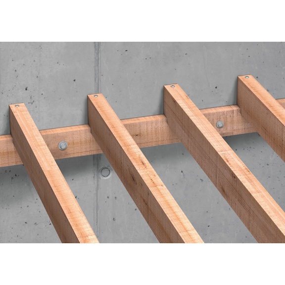
Application area | Individual fixing point with approval: | Normal weight concrete C20/25 to C50/60 (cracked and uncracked concrete) | Especially suitable for fixtures in wooden construction applications in concrete: | Mounting of e.g. support beams, sleepers, inferior purlins, canopies, wooden substructures, etc.
Fastenings under seismic conditions in earthquake areas
Fastenings under exposure to fire | Mounting of e.g. support beams, sleepers, inferior purlins, canopies, wooden substructures, etc. | Fastenings under seismic conditions in earthquake areas | Fastenings under exposure to fire | W-BS/S (galvanised steel) may only be used in dry indoor room conditions | For use in concrete < C20/25 and pressure-resistant natural stone (without approval)
Tehnical Information
Anchor size: 10 mm | Anchor length (l): 180 mm | Attachment height (t fix 1): 125 mm | Attachment height (t fix 2): 105 mm | Attachment height (t fix 3): 95 mm | Thread diameter: 12 mm | Nominal drill-bit diameter (d 0): 10.0 mm | Drill hole depth (h 1.1): 65 mm | Drill hole depth (h 1.2): 85 mm | Drill hole depth (h 1.3): 95 mm | Embedding depth (h nom1): 55 mm | Embedding depth (h nom2): 75 mm | Embedding depth (h nom3): 85 mm | External drive: WS15 | Material: Steel | Surface: Zinc plated | Washer diameter: 44 mm | Through-hole in the component to be connected (d f): 14.0 mm | Head type: Hexagon head | Type description: W-BS type S