


Description
Specification
Highest loads and efficient installation. For flush-mount installation of e.g. railings or handrails, zinc-plated steel | For anchorage in concrete and masonry
Extremely flexible application thanks to up to three effective anchorage depths (size 6-10)
Fastening can be adjusted up to two times after installation (size 6-10), for example in order to align railings or anchor plates (please refer to the installation instructions)
Very high loads
Very low spacing and edge distances thanks to very low expansion effect
Very fast and easy installation and immediate load-bearing capacity
Attractive, flush-mount installation possible | For anchorage in concrete and masonry | Extremely flexible application thanks to up to three effective anchorage depths (size 6-10) | Fastening can be adjusted up to two times after installation (size 6-10), for example in order to align railings or anchor plates (please refer to the installation instructions) | Very high loads | Very low spacing and edge distances thanks to very low expansion effect | Very fast and easy installation and immediate load-bearing capacity | Attractive, flush-mount installation possible | Proof of Performance | European Technical Assessment ETA-16/0043 for individual fixing point, option 1, cracked and uncracked concrete: | Static and quasi-static action (dia. 6-10)
Seismic action, performance category C1 (dia. 6-10) and C2 (dia. 8-10)
Fire resistance R30, R60, R90, R120 | Static and quasi-static action (dia. 6-10) | Seismic action, performance category C1 (dia. 6-10) and C2 (dia. 8-10) | Fire resistance R30, R60, R90, R120 | European Technical Assessment ETA-23/0196 for anchorage in masonry | Static and quasi-static action (dia. 5-10)
Fire resistance R30, R60, R90, R120 (dia. 5-6) | Static and quasi-static action (dia. 5-10) | Fire resistance R30, R60, R90, R120 (dia. 5-6) | European Technical Assessment ETA-16/0128 for anchors in a redundant non-structural system: | Cracked and uncracked concrete, (dia. 5 and dia. 6)
Hollow-core prestressed concrete ceilings C30/37-C50/60, (dia. 6)
Fire resistance R30, R60, R90, R120 | Cracked and uncracked concrete, (dia. 5 and dia. 6) | Hollow-core prestressed concrete ceilings C30/37-C50/60, (dia. 6) | Fire resistance R30, R60, R90, R120 | DIBt National technical approval/general type approval Z-21.1-2075 as bonded screw anchor for anchorage in concrete (dia. 10 ), type SK countersunk head | Use in combination with WIT-BS injectable mortar as WIT-BS bonded screw anchor
In reinforced and non-reinforced and cracked and uncracked concrete C20/25 to C50/60 | Use in combination with WIT-BS injectable mortar as WIT-BS bonded screw anchor | In reinforced and non-reinforced and cracked and uncracked concrete C20/25 to C50/60 | Fire resistance rating when exposed to fire according to the standard temperature time curve in masonry (Mz, KSL, KS) and reinforced concrete, (dia. 5 and dia. 6) – expert report no 2101/173/18 – 2018 | Notice | From size 8, we recommend the use of a suitable tangential impact driver for installation. The recommended maximum nominal torque must be observed. When used in masonry, the stone-specific installation data according to ETA-23/0196 must be observed. | Application area | Railings
Handrails
Adjustment – subsequent aligning possible | Railings | Railings | Railings | Handrails | Handrails | Handrails | Adjustment – subsequent aligning possible | Adjustment – subsequent aligning possible | Adjustment – subsequent aligning possible | Create the drill hole
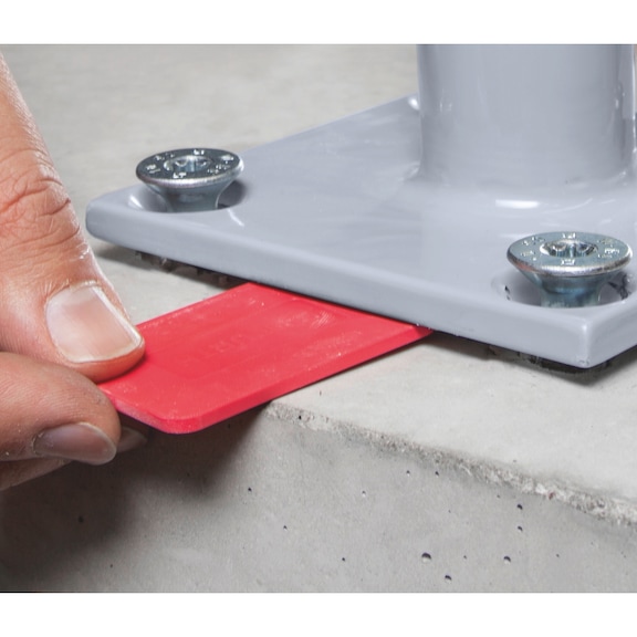
Clean the drill hole
Place screw
Screw in the screw
Considered installed when the head is close fitting | Create the drill hole | Create the drill hole | Create the drill hole | Clean the drill hole | Clean the drill hole | Clean the drill hole | Place screw | Place screw | Place screw | Screw in the screw | Screw in the screw | Screw in the screw | Considered installed when the head is close fitting | Considered installed when the head is close fitting | Considered installed when the head is close fitting | Screw out the screw max. 2x each by max. 10 mm. Underlay. Screw in
Considered installed when the head is close fitting. Lining max. 10 mm. The required embedment depth must be maintained as a minimum | Screw out the screw max. 2x each by max. 10 mm. Underlay. Screw in | Screw out the screw max. 2x each by max. 10 mm. Underlay. Screw in | Screw out the screw max. 2x each by max. 10 mm. Underlay. Screw in | Considered installed when the head is close fitting. Lining max. 10 mm. The required embedment depth must be maintained as a minimum | Considered installed when the head is close fitting. Lining max. 10 mm. The required embedment depth must be maintained as a minimum | Considered installed when the head is close fitting. Lining max. 10 mm. The required embedment depth must be maintained as a minimum | Locate the tensioning strand
Mark the tensioning strand and locate the next one
Mark the tensioning strands. Specify the drilling range
Create the drill hole. Observe spacing
Clean the drill hole
Screw in the screw
Considered installed when the head is close fitting. Observe the embedment depth/mirror thickness | Locate the tensioning strand | Locate the tensioning strand | Locate the tensioning strand | Mark the tensioning strand and locate the next one | Mark the tensioning strand and locate the next one | Mark the tensioning strand and locate the next one | Mark the tensioning strands. Specify the drilling range | Mark the tensioning strands. Specify the drilling range | Mark the tensioning strands. Specify the drilling range | Create the drill hole. Observe spacing | Create the drill hole. Observe spacing | Create the drill hole. Observe spacing | Clean the drill hole | Clean the drill hole | Clean the drill hole | Screw in the screw | Screw in the screw | Screw in the screw | Considered installed when the head is close fitting. Observe the embedment depth/mirror thickness | Considered installed when the head is close fitting. Observe the embedment depth/mirror thickness | Considered installed when the head is close fitting. Observe the embedment depth/mirror thickness | European Technical Assessment ETA-16/0043 for individual fixing point, option 1, cracked and uncracked concrete: | Static and quasi-static action (dia. 6-10)
Seismic action, performance category C1 (dia. 6-10) and C2 (dia. 8-10)
Fire resistance R30, R60, R90, R120 | Static and quasi-static action (dia. 6-10) | Seismic action, performance category C1 (dia. 6-10) and C2 (dia. 8-10) | Fire resistance R30, R60, R90, R120 | European Technical Assessment ETA-23/0196 for anchorage in masonry | Static and quasi-static action (dia. 5-10)
Fire resistance R30, R60, R90, R120 (dia. 5-6) | Static and quasi-static action (dia. 5-10) | Fire resistance R30, R60, R90, R120 (dia. 5-6) | European Technical Assessment ETA-16/0128 for anchors in a redundant non-structural system: | Cracked and uncracked concrete, (dia. 5 and dia. 6)
Hollow-core prestressed concrete ceilings C30/37-C50/60, (dia. 6)
Fire resistance R30, R60, R90, R120 | Cracked and uncracked concrete, (dia. 5 and dia. 6) | Hollow-core prestressed concrete ceilings C30/37-C50/60, (dia. 6) | Fire resistance R30, R60, R90, R120 | DIBt National technical approval/general type approval Z-21.1-2075 as bonded screw anchor for anchorage in concrete (dia. 10 ), type SK countersunk head | Use in combination with WIT-BS injectable mortar as WIT-BS bonded screw anchor
In reinforced and non-reinforced and cracked and uncracked concrete C20/25 to C50/60 | Use in combination with WIT-BS injectable mortar as WIT-BS bonded screw anchor | In reinforced and non-reinforced and cracked and uncracked concrete C20/25 to C50/60 | Fire resistance rating when exposed to fire according to the standard temperature time curve in masonry (Mz, KSL, KS) and reinforced concrete, (dia. 5 and dia. 6) – expert report no 2101/173/18 – 2018
Application
Application area | Anchorages in concrete, individual fixing point with approval (dia. 6-10): | In normal weight concrete C20/25 to C50/60 (cracked and uncracked concrete) | Anchors in a redundant non-structural system in concrete, with approval: | In normal weight concrete C20/25 to C50/60 (cracked and uncracked concrete), (dia. 5 and dia. 6)
In hollow-core prestressed concrete ceilings C30/37-C50/60, (dia. 6) | In normal weight concrete C20/25 to C50/60 (cracked and uncracked concrete), (dia. 5 and dia. 6) | In hollow-core prestressed concrete ceilings C30/37-C50/60, (dia. 6) | Anchorages in masonry with approval (dia. 5-10): | In solid calcium silicate block and perforated block
In solid block masonry brick | In solid calcium silicate block and perforated block | In solid block masonry brick | Specifically designed for attractive, flush-mount installation | Suitable for fastening medium to heavy loads in concrete and light to medium loads in masonry: | Fastening of e.g. staircase railings and balcony balustrades, handrails, steel structures, wooden substructures, metal profiles etc. in in-place installation
Fastenings subject to seismic activity in earthquake-prone areas (only concrete)
Fastenings subject to exposure to fire | Fastening of e.g. staircase railings and balcony balustrades, handrails, steel structures, wooden substructures, metal profiles etc. in in-place installation | Fastenings subject to seismic activity in earthquake-prone areas (only concrete) | Fastenings subject to exposure to fire | W-BS/S (galvanised steel) may only be used in dry indoor room conditions | For use in concrete < C20/25 and pressure-resistant natural stone (without approval)
Tehnical Information
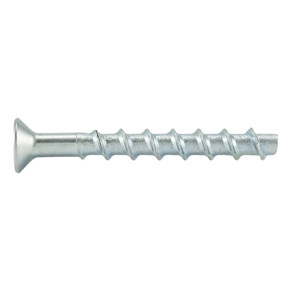
Anchor size: 10 mm | Anchor length (l): 100 mm | Attachment height (t fix 1): 45 mm | Attachment height (t fix 2): 25 mm | Attachment height (t fix 3): 15 mm | Thread diameter: 12 mm | Nominal drill-bit diameter (d 0): 10.0 mm | Drill hole depth (h 1.1): 65 mm | Drill hole depth (h 1.2): 85 mm | Drill hole depth (h 1.3): 95 mm | Embedding depth (h nom1): 55 mm | Embedding depth (h nom2): 75 mm | Embedding depth (h nom3): 85 mm | Head diameter (d sk): 22 mm | Internal drive: TX50 | Head type: Countersunk head | Material: Steel | Through-hole in the component to be connected (d f): 14.0 mm | Surface: Zinc plated | Type description: W-BS type SK